Troubleshooting
Things to Check First
Console log
Check whether the fanuc_driver is outputting any errors to the console.
[FR_HW_Interface]: Failed to create TCP connection at: *.*.*.*
The fanuc_driver failed to establish RMI’s TCP connection to the robot controller.
Check the network status to the robot controller using the
pingcommand, or access the robot controller’s IP address with a browser and confirm that the robot’s homepage is displayed.This error can also occur if R912 Remote Motion is not installed on the robot controller.
IO configuration failed with error code: 2
This error indicates that the synchronized I/O configuration does not match the robot controller’s I/O assignments. See Configuring high-frequency I/O for details.
/fanuc_gpio_controller/robot_status topic
A topic /fanuc_gpio_controller/robot_status shows the current status.
in_erroris true
The robot controller is in error status. Check the alarm screen on the Teach Pendant.
tp_enabledis true
The Teach Pendant is enabled. Keep the Teach Pendant disabled while the fanuc_driver is controlling the robot.
motion_possibleis false
The robot controller is not in Stream Motion control mode.
When an alarm occurs on the robot controller, restart the hardware_component by switching its status to
inactiveand re-switching it toactiveto re-establish the connection.
Robot controller’s error
Check the alarm screen on the Teach Pendant.
Common Issues
I cannot command motion and I received a RMI session timeout error
The controller will automatically terminate the connection when the client fails to send a command/instruction packet within the Remote Motion Interface (RMI) timeout (default is 60 minutes).
Once the connection is terminated, the client needs to be restarted.
For R-30iB Plus:
To change the default time, modify the system variable $rmi_cfg.$discnt_tim. Setting this variable to 0 disables the timeout check.
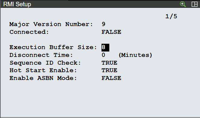
For R-50iA: To change the default time, go to the MENU->UTILITIES->RMI Position/Setup->SETUP screen on the teach pendant. Setting “Disconnect Time” to 0 disables the timeout check.
I cannot command motion and received a SYST-322 Auto Status Check timeout alarm
When the robot is keep moving for longer than the Auto Status Check timeout setting, a SYST-322 Auto status check timeout alarm will be posted and the robot will stop.
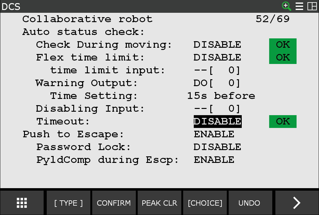
This alarm can be suppressed in one of two ways: change the timeout value or disable the timeout. Both are safety features which require applying DCS changes and cycling power.
The following shows the screen for the Auto Status Check timeout.
I cannot command motion after accessing the teach pendant or E-stop
When running external motion commands through the ROS 2 controller interface, the external motion will stop as soon as there is a servo fault on the controller, triggered by such things as turning on the teach pendant or performing an E-stop. Afterwards, the ROS driver will not be able to send commands to the robot again until the controller’s fault is cleared and the ROS driver regains motion control. Refer to Alarm Recovery for details.
I get occasional robot motion faults
This may be attributed to your PC’s high CPU load; try the following suggestions to help alleviate the high CPU load:
Computers with high CPU loading may miss their command send windows, causing the robot to fault. You might need to adjust your real-time process priorities to ensure the timing of all command send windows or limit the number of concurrent tasks.
The Ubuntu PC should have the real-time kernel enabled.
I cannot command motion and received a MOTN-615 ST:Please Disable Brake Control. alarm
When you add J519 to an existing robot controller, you must manually disable the brake control function.
For R-30iB Plus:
Go to the MENU->SYSTEM->System Variables screen on the teach pendant.
Set $PARAM_GROUP[1].$SV_OFF_ENB[1to9] to FALSE and repower the robot controller.
For R-50iA:
Go to the MENU->SETUP->Brake Control screen on the teach pendant. For all axes, set the “BRK_CTRL” value to DISABLE and repower the robot controller.
J3 value differs from the value on the Teach Pendant
In FANUC’s coordinate system, the J3 axis of 6-axis robots is defined as the angle from the horizontal plane.
The J3 value in ROS 2 corresponds to the J2J3 Interaction angle shown on the Teach Pendant, which is the sum of the J2 and J3 angles.